javaKUKA play KUKA in Java
Interact
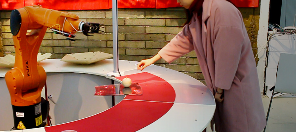
Connecting a camera to a KUKA robot enables the robot to observe the environment and react responsively. The low-level information captured by the camera, namely the pixels, is transformed into a certain meaningful signal that constantly informs the robot’s motion. This post briefly introduces the connection and the communication between the vision system and KUKA.
1. System architecture
One can either develop robot’s software interpreting low-level signals (pixels) and reacting so that the robot has the a brain or let the camera’s software transform the original signals into structured data before feeding it to the robot so the camera is both the eye and the brain. Our example follows the second approach, as the commercial vision system (COGNEX) already integrates intelligent functionalities, such as pattern matching, into the standalone camera. We connected a COGNEX In-Sight 1100 with a KUKA KR6 through the EtherNet/IP protocol. The Ethernet cable connects the camera with the X66 of the C4 compact controller.
We used WorkVisual to configure the digital inputs (e.g., $IN[200] to $IN[231] receive a 32-bit integer value, which represents the x-coordinate) from the EtherNet/IP communication. On the camera side, In-Sight explorer was used to configure the format of the output data to match the WorkVisual settings. The figure below illustrates the system architecture.
2. Communication
The COGNEX camera recognizes the current workpiece (whose pattern is predefined in COGNEX’s In-sight Explorer) and computes the workpiece’s position X, Y, and orientation A. We convert the three real variables into 32-bit integers by multiplying them by 1000 respectively. Eventually, the camera will constantly send the three integers to the KUKA controller through EtherNet/IP.
For KUKA, one needs to firstly define three integers (SIGNAL) variables that receive the data from the camera (in KRC:/ R1 / System /config.dat):
SIGNAL INPUT X $IN[200] TO $IN[231]
SIGNAL INPUT Y $IN[232] TO $IN[263]
SIGNAL INPUT A $IN[264] TO $IN[295]
and a FRAME variable whose values will be replaced by real-time data:
FRAME pos={X 91, Y 188, Z 128, A 0, B 0, C 0}
Second, the main program (.src) uses the real-time values of X, Y, and A to plan the robot motion, for example, to reach the recognized workpiece’s position:
FOR NI=1 TO 10
wait sec 2
pos.x= 615+ INPUT X *0.001
pos.y= -180+ INPUT Y *0.001
pos.c= INPUT A *0.001
PTP pos C_DIS
END FOR
In real applications, the codes could be much more complicated because of issues of the stability of communication, smoothness of motion, collision, and safety.
3. Gripper
We used a digital signal from KUKA to control a gripper, for example, ON: grasping; OFF: leasing. To control the gripper, one needs to
1) Wire the gripper to KUKA’s digital I/O. Some robots have an X41 connection on the arm so we can easily wire the X41 to the gripper. Otherwise, we need to connect the EtherCAT (in C4 controller) to the gripper. One can switch a specific digital output (Display / Inputs/ outputs / Digital I/O) and see the corresponding LED switch on the EtherCAT module.
2) Manipulate the digital output (corresponding to a specific slot of X41) in the main program (.src) to control the gripper. For instance:
pos.z= 100
$OUT[2]=false
pos.z= 0
PTP pos C DIS
$OUT[2]=true
wait sec 0.5
pos.z= 100
PTP pos C DIS
which opens the gripper ($OUT[2]=false) before grasping and closes the gripper ($OUT[2]=true) when grasping at the right position.